
Simulation of Cutting Forces during Milling
10 Jan 2015This project was also part of the Numerical Control of Machine Tools (ME548) course that I took last semester. The goal of the project was to develop a mathematical model for a 2-fluted end-mill in order to simulate the forces developed under different cutting conditions.
Experimental data was collected using a dynamometer for four test cases. The spindle speed, feed rate and axial depth of cut were all kept constant, while the radial depth of immersion was varied. The four immersion cases used were quarter immersion, half immersion, three-quarter immersion, and full immersion (slotting).
Orthogonal cutting coefficients were provided for 6061 aluminum, along with the relevant tool geometry (helix angle and rake angle). Using this information, I developed a model using Brown and Armarego’s cutting equations and Stabler’s chip flow rule and implemented it in MATLAB.
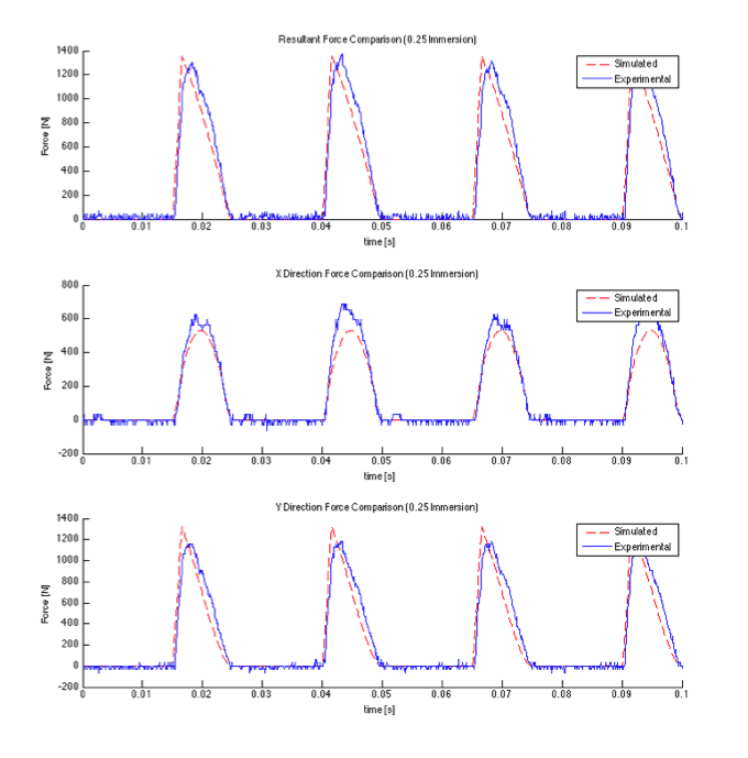
Once the bugs were eliminated from the MATLAB code, I simulated the four test cases and overlayed the simualation and experimental data for the X, Y and resultant forces. The plots for two of the test cases can be seen below:
Quarter Immersion:
Three-quarter Immersion:
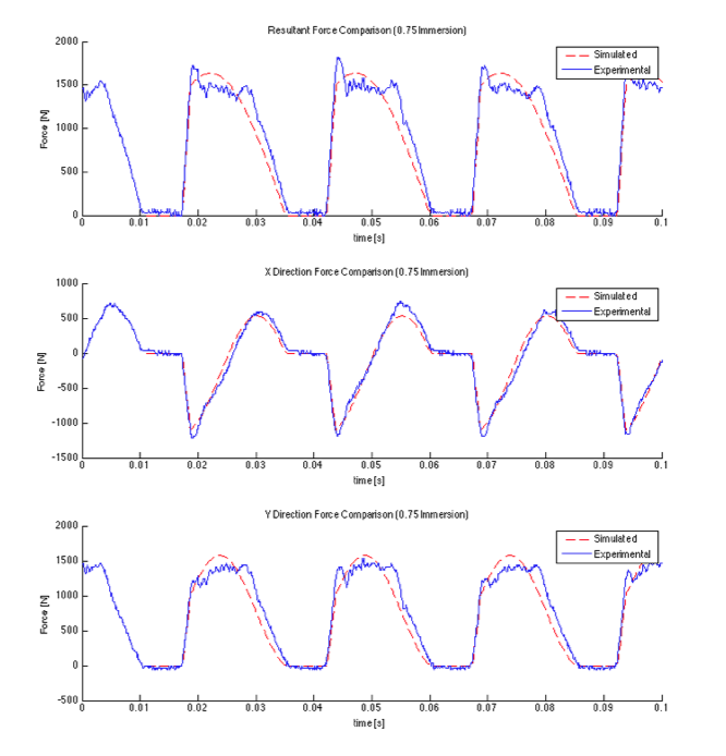
Both plots show that the simulation captures the behaviour of the end mill quite accurately. Ignoring measurement and vibrational noise, the discrepancy between the curves comes from tool wear which distorts the force profile for the experimental data. In fact, the predictive model can be used as a indicator of just how worn the particular tool is, and even whether it needs to be replaced.
One thing I found particularly interesting (although unsurprising) was the comparison between the different cutting cases. The plot below shows all four cases overlaid and aligned:
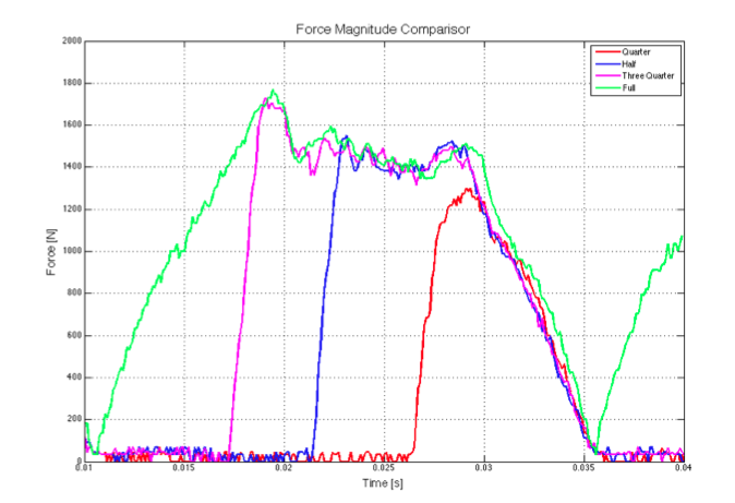
Because the same tool was used for each of the cutting cases, each one produces an almost identical force profile during the part of the cycle in which a tooth is engaged. Very cool.